Contact
Want to go in contact? You can find ways to do so below. I mostly respond through email though. Currently open to any offers.
To summarize this was about applying my knowledge of microprocessor systems that largely involved learning through the EsduinoXtreme. The microprocessor was coded in Assembly through CodeWarrior and connected with a USBDM to be programmed. The project required a circuit that took an input scaled it, and converted it to digital values to be displayed using Matlab. Essentially it was a basic analog to digital circuit (ADC). Below will contain pictures of the project but no schematics or source code. This was a project completed for the microprocessor systems class.
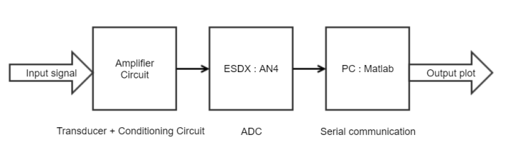 Figure 1 : The block diagram of the entire setup
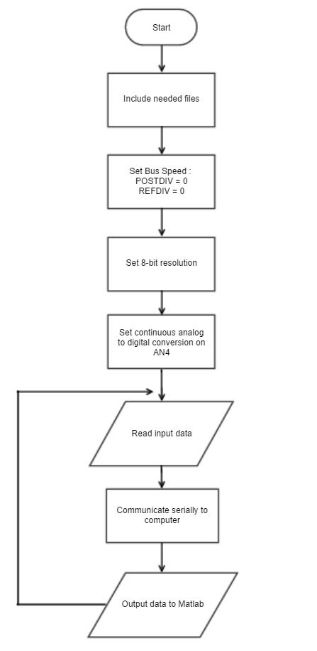
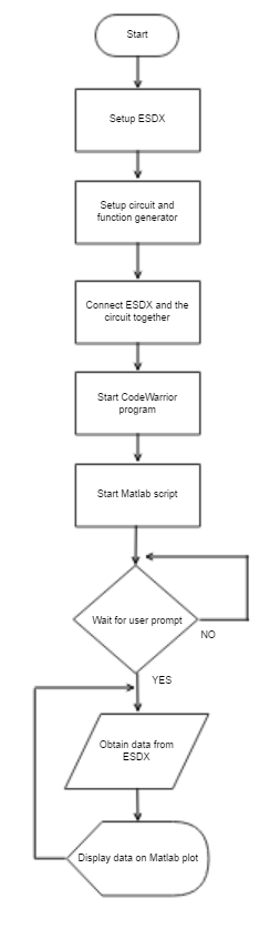 Figure 2 : The flow chart for the entire setup and the ESDX
 Figure 3 : The amplifying circuit built
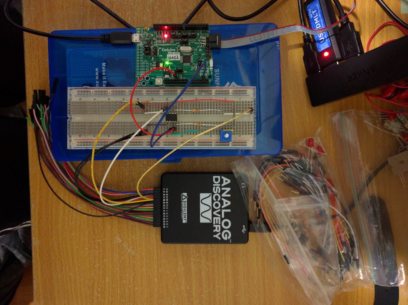 Figure 4 : The entire setup
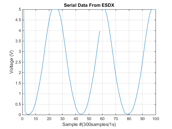 Figure 5 : Matlab plots on a sine wave input
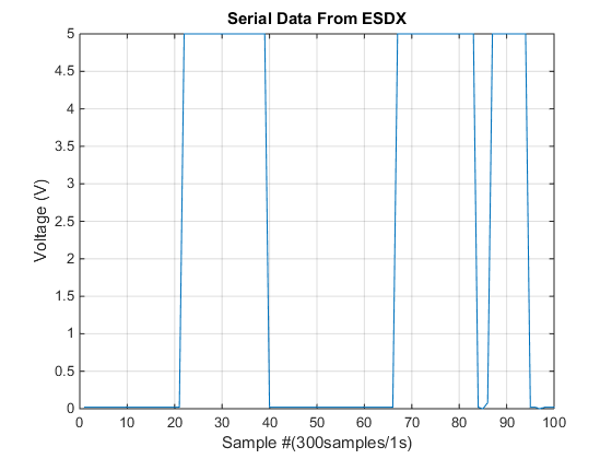 Figure 6 : Matlab plots on a square wave input
An amplifying circuit was constructed to scale the input signal to a suitable range for the ESDX. The circuit was a simply 2 op-amp circuit with capacitors and resistors. Choosing the correct circuit was not too diffult as it was very obvious we wanted X2 of the input. This all occured around the same time during our circuits course where we began to use OP-AMPs for gain. A very shocking coincidence.
The ESDX was programmed in Assembly that involved configuring which pin was used as input and output. This was done the CodeWarrior IDE, which had an option of coding in C instead. Since aim of the class was to teach Assembly, we did not use C. It also involved setting the sampling frequency and the bit-resolution. We weren't given the code, but had past labs to look on. It was merely a matter of setting the right pins to the correct configurations.
Matlab was the software used to plot the results of the ADC. Anything else could have been used, but Matlab was used since it was very simple to configure it to work with a serial input from the ESDX along with the ease of plotting. At the point of completion, I'm not sure anything else coudl've have been used. In theory Octave should have worked. Also putting the results in a text document would have worked as well, but seemed like an extra step if all we wanted to do was plot it.
In the end the project worked but was not perfect. The output plots were acceptable but not entirely clean most likely due to poor adjustment of the clock inside the ESDX possibly improper use of Nyquist theorem. The designed circuit(conditioning and amplifier) worked flawlessly. Generally, I have a deeper appreciation of how this process works since normally it works flawlessly while mines was not so great. That being said, I did not find it a hard project to do. It could've been better, but it may have been a case of "in theory, but in practice".